

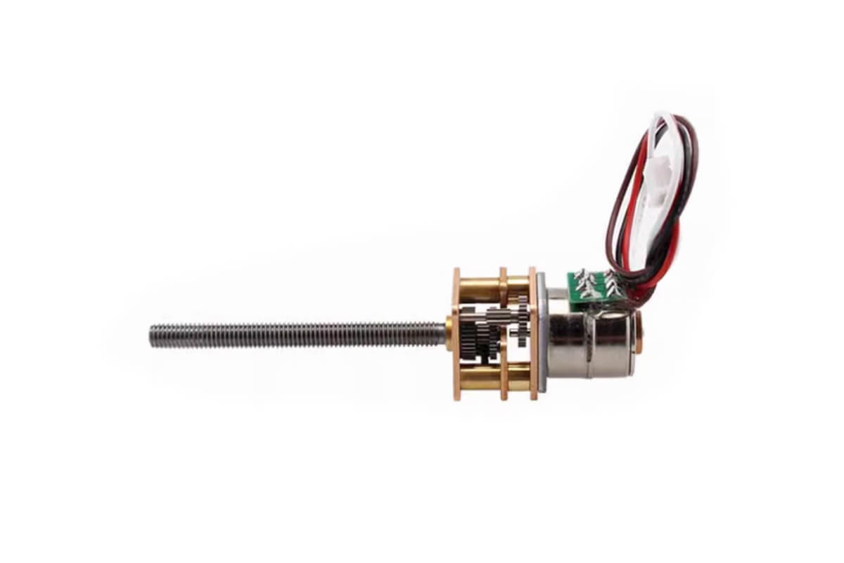
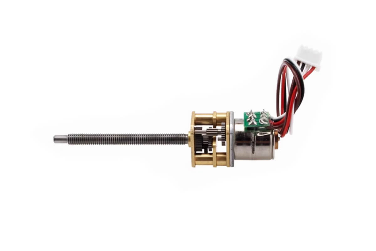
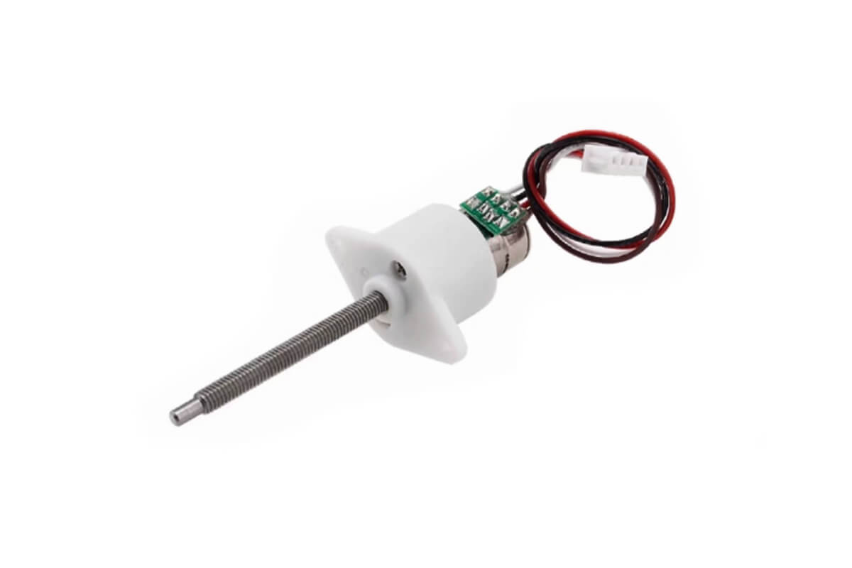
10mm Mini Stepper Gear Motor – 20mm Type Model NFP-GM12-10BY-M3-L
$18.50
Enhance your projects with our reliable 10mm Mini Stepper Gear Motor. Experience smooth stepper control and durability for various applications!
Contact us for a quotation for production quantities, customizations and integration.
Permanent Magnet Brushless Stepper Gear Reduction Motor Parameters
Product Overview
The NFP-GM12-10BY-M3-L is a compact permanent magnet brushless stepper gear reduction motor. Therefore, it is suitable for small mechanical systems that need accurate positioning and stable output torque.
In addition, this motor uses an M3 standard screw shaft and an all-metal gear reducer. As a result, it offers better wear resistance during repeated operation.
Main Product Features
- Stepper control: It converts electrical pulse signals into angular displacement. Therefore, it is easy to use for intelligent control.
- All-metal gears: The gearbox adopts metal gear material. As a result, it is more wear-resistant and durable.
- Threaded shaft: The motor uses an M3 standard screw shaft. In addition, a flange nut is available if required.
- Compact design: The small motor body saves installation space. Moreover, it supports compact product design.
- Typical applications: It can be used in intelligent robots, manipulators, smart furniture, focusing systems, miniature pan/tilts, and other precision mechanisms.
Reduction Ratio Selection Guide
The reduction ratio affects both step angle and output torque. For example, a lower reduction ratio provides a larger step angle and lower torque.
However, a higher reduction ratio provides a smaller step angle and greater torque. Therefore, users can choose the proper ratio according to speed, torque, and positioning accuracy requirements.
Basic Motor Specifications
The following table shows the basic electrical and mechanical parameters. In addition, it helps engineers confirm voltage, current, shaft size, and wiring before testing.
| Motor Model | NFP-GM12-10BY-M3-L |
|---|---|
| Motor Size | Φ10mm*12mm*20mm |
| Shaft Diameter | ΦM3 |
| Output Shaft Length | 33.6mm (A/B-type) / 32.3mm (C-type) |
| Phase Resistance | 39Ω±7% / Phase |
| Phase Current | 128mA / Phase |
| Phase Inductance | 14.3 mH / Phase |
| Step Angle | 18° / Step |
| No. of Phases | 2Phases 4Wires |
| Max. Starting Frequency | 1200PPS Min. |
| Max. Response Frequency | 900PPS Min. |
| Rated Voltage | 5V DC (Driver IC: L6219) |
| Weight | Appr. 11g |
| Wires Sequence | Red A- / White A+ / Black B- / Brown B+ |
Gear Ratio and Torque Options
The following table shows available reduction ratios and torque options. Therefore, it helps engineers compare different configurations during product design.
Moreover, the precise ratio data is useful for calculating output step degree and positioning resolution. As a result, it can support more accurate prototype selection.
| Ratio | Precise Ratio | Step Degree | Holding Torque | Pull-out Torque |
|---|---|---|---|---|
| 1: 10 | 9.68 | 1.86° | 0.12 kgf.cm | 0.03 kgf.cm |
| 1: 20 | 19.36 | 0.93° | 0.24 kgf.cm | 0.06 kgf.cm |
| 1: 30 | 29.47 | 0.61° | 0.36 kgf.cm | 0.09 kgf.cm |
| 1: 50 | 51.1 | 0.35° | 0.6 kgf.cm | 0.15 kgf.cm |
| 1: 100 | 99.3 | 0.18° | 1.2 kgf.cm | 0.3 kgf.cm |
| 1: 150 | 150.96 | 0.12° | 1.8 kgf.cm | 0.45 kgf.cm |
| 1: 210 | 209.76 | 0.086° | 2.5 kgf.cm | 0.63 kgf.cm |
| 1: 298 | 297.9 | 0.06° | Max. 3 kgf.cm | 0.9 kgf.cm |
| 1: 380 | 379.16 | 0.047° | Max. 3 kgf.cm | 1.1 kgf.cm |
Brushless Screw Shaft Stepper Gear Reduction Motor Outline Drawing
Motor Structure Options
The motor is available in three mechanical versions. Therefore, users can choose the proper structure according to the installation space, mounting method, and protection requirement.
- A-type: Straight thread shaft design. Therefore, it is suitable for simple screw shaft applications.
- B-type: Thread shaft with location pillar. As a result, it can improve positioning during assembly.
- C-type: Thread shaft with location pillar and protective shell. In addition, it provides better structural protection.

A-type Straight Thread
The A-type version uses a straight M3 threaded shaft. Therefore, it is suitable for compact mechanisms that require direct screw-driven motion.
In addition, this structure is easy to integrate into simple linear movement systems.

B-type with Location Pillar
The B-type version includes a location pillar. As a result, it helps improve positioning during assembly.
Moreover, it is suitable for applications that require a stable mounting reference.

C-type with Location Pillar & Protective Shell
The C-type version includes both a location pillar and a protective shell. Therefore, it is suitable for designs that need better protection around the motor body.
In addition, the shell can help improve the overall assembly structure.

Flange Coupling Option
If a flange coupling is required, please note this requirement when placing an order. In this way, the motor can be prepared according to your assembly needs.
Furthermore, this note helps avoid mismatched accessories during installation.

Long Shaft M3 Thread Shaft BLDC Step Motors Connection Diagram
Terminal and Wire Information
The terminal uses a 1.25-4Y wiring connector. Moreover, the wire specification is GB1571 30/UL, AWM, 105°.
Therefore, please follow the wiring sequence carefully during connection.
- Red wire: A-
- White wire: A+
- Black wire: B-
- Brown wire: B+
Wiring Diagram
The wiring diagram below shows the terminal sequence. In addition, it helps users confirm the correct coil connection before testing the motor.
Finally, correct wiring can reduce the risk of abnormal rotation or motor failure.

Keywords:
step gear motor, stepper dc gear motor, stepping geared motor
1.Payment methods : Paypal, T/T
Shipping:
1.Delivery: DHL/FedEx 3-5 days.
2.Item will be shipped within 1-3 business days after the payment.
3.If you haven’t received the item on the Delivery Time, pls contact us by email if you have any questions. Normally, we will give you a reply within 24 hours, if not, pls check the spam of your email box. We will do our best to help you solve the problems.
4.Please make sure your address is matched with the finally shipping address before you pay.
FAQ
Q: If customized, what information should you provide?
A: You need to provide the basic specification of the motor, such as: Dimensions, Sizes Applications, Voltage, Speed and Torque. It’s better to offer application prototype drawings to us if possible.
Q: What’s your main motors?
A: Diameter 4mm~42mm Dc Micro Motor And Gear Motor, Auto Dc Motor, Electric Motor, Gear Motor, Mini Dc Motor, Brush Dc Motor, Brushless Dc Motor, Spur Gear Motor, Micro Motor, Vibration Motor Etc.
Q: What’s the main application of the micro dc motor?
A: Our mini DC motors are widely used in Home Applications, Office Equipment, Health-Care Application, Sanitation Industry, High-Class Toy, Banking System, Electronic and Electrical Tools, Automation Industry, Bank Equipments, Payment Equipments, Vending Machines, Power Door Lock, Electric Door Lock.


Ashwin Kumar –
For the price, this motor is a fantastic deal. I used it in a small 3D printer build, and it worked perfectly. It’s responsive and provides good torque for small, lightweight systems.