


Stepper Motor Driver Controller 2-Phase, 4-Wire
$14.50
Maximize efficiency in your applications using the 2 phase 4 wire stepper motor driver. Explore unmatched functionality and reliability now!

Stepper Motor Simple Driver Product Information
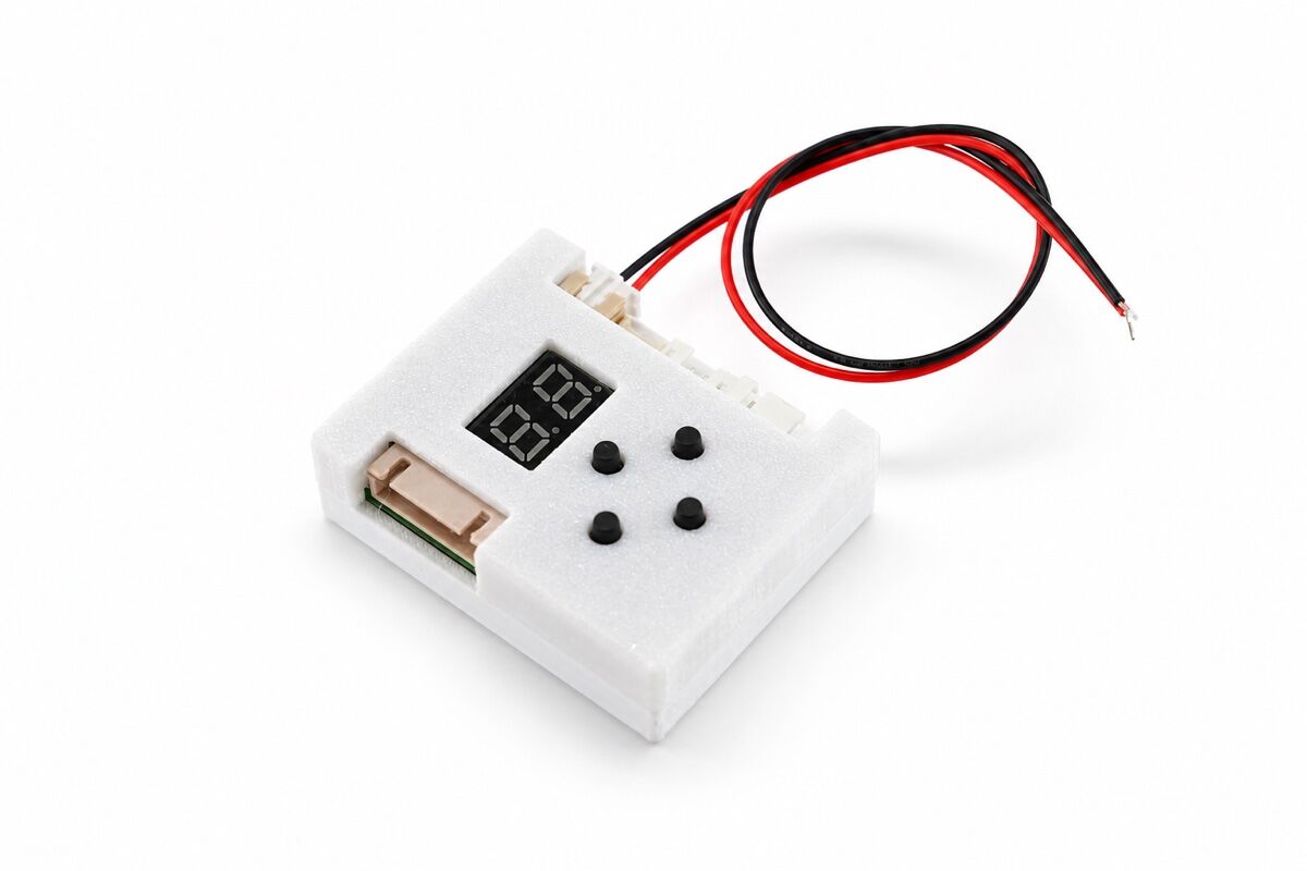
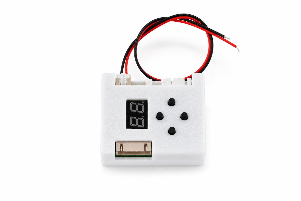
The NFP-Motor Stepper Motor Simple Driver is a compact driver module for small stepper motor control. It supports DC 5-36V power input and can be used with or without housing.
First, this driver supports speed adjustment, direction control, enable control, and automatic reciprocating motion. Also, it has a compact size for small equipment and DIY projects.
In addition, the driver includes button control and a 6P control port. Therefore, users can test motors directly or connect external control signals.
Main Product Features
- First, wide input range: The power input supports DC 5-36V.
- In addition, compact size: The driver is available with or without housing.
- Also, speed control: The driver supports 0-29 gear adjustment.
- Next, direction control: Direction A and Direction B buttons support motor rotation control.
- Finally, reciprocating mode: The driver can support automatic back-and-forth motion.
Product Information
Next, the table below helps users check brand, model, input voltage, dimensions, weight, and gear level data. Therefore, it is easier to confirm whether this stepper motor driver fits the final product design.
| Parameter | Specification |
|---|---|
| Brand | NFP-Motor |
| Model | Stepper Motor Simple Driver |
| Power Input | DC 5-36V |
| Dimensions | Without housing: width 38mm, length 48mm With housing: 42mm*52mm*16mm |
| Weight | Without housing: 13g; with housing: 27g |
| Up/Down Gear Levels | 0-29 gear adjustment Reference setting value PPS/HZ (reference value, not an exact value) |
| Note | Different motors match different gear levels; not all gear levels can operate normally on the same motor. |
Also, different motors need different gear levels. As a result, users should test the motor and load together before final use.

Control Port 6P Interface
First, the 6P control port supports PUL, DIR, and EN signals. Therefore, users can connect external signals for speed, direction, and enable control.
| Signal Pin | Signal Name | Function Description | Signal Voltage Range |
|---|---|---|---|
| 1 | PUL | Speed control frequency input Input frequency range 0Hz-2KHz Motor speed changes continuously | DC 5-36V |
| 2 | DIR | Direction control signal. Used to control forward or reverse motor rotation. | DC 5-36V |
| 3 | EN | Enable control signal. When this signal is active, the PUL and DIR signals take effect. | DC 5-36V |
In addition, the PUL input supports 0Hz-2KHz frequency control. As a result, the motor speed can change continuously within the supported range.
General Operation Test
Next, the button functions help users test the driver without a complex control system. Also, the same buttons can enter automatic reciprocating mode.
| Button Name | Single Press Function | No Combination Operation Function |
|---|---|---|
| Speed + | During operation, increases the motor speed. A total of 29 gear levels are available. Note: Different motors match different gear levels; not all gear levels can operate normally. | Press simultaneously with the “Speed -” key to enter automatic reciprocating mode. |
| Speed – | During operation, reduces the motor speed. A total of 29 gear levels are available. Note: Different motors match different gear levels; not all gear levels can operate normally. | Press simultaneously with the “Speed +” key to enter automatic reciprocating mode. |
| Direction A | 1. Start: In the stopped state, press this key and the motor starts in direction A. 2. Direction change: During operation, press this key and the motor immediately changes to direction A. 3. Set boundary: In automatic reciprocating mode, set the current position as the direction A boundary point. | Press once to rotate; press again to pause. |
| Direction B | 1. Start: In the stopped state, press this key and the motor starts in direction B. 2. Direction change: During operation, press this key and the motor immediately changes to direction B. 3. Set boundary: In automatic reciprocating mode, set the current position as the direction B boundary point. | Press once to rotate; press again to pause. |
Therefore, users can adjust speed and direction from the board buttons. However, each motor and load should be tested to confirm the suitable gear level.
Automatic Reciprocating Run Program Operation Instructions
First, automatic reciprocating mode helps the motor move back and forth using a memorized step count. Therefore, it is useful for simple repeated travel control.
| Operation Step | Operation Description |
|---|---|
| 1. Enter Mode | After the device is powered on, press and hold the “Speed +” and “Speed -” keys at the same time to enter automatic reciprocating mode. |
| 2. Initial Operation | After entering the mode, the device starts one-way operation with a large default step count (about 65500 steps) until it reaches the boundary. |
| 3. Set Travel | Before the device reaches the boundary for the first time, press the “Direction” key at any time. The device immediately memorizes the step count from the starting point to the current position. |
| 4. Start Reciprocating | After the travel is set, the device starts automatic back-and-forth reciprocating motion using the memorized step count as the single-trip distance. |
| 5. Adjust Speed | During reciprocating motion, the speed can be manually adjusted at any time. |
| 6. Reset | To change the travel, press the “Direction” key again while the device is running in one direction. The device updates the single-trip step count to the distance from the current position to the starting point. |
| Note | Frequently pressing the “Direction” key will cause the memorized single-trip step count to become smaller and smaller. |
Also, users can adjust the speed during reciprocating motion. As a result, the same setup can support different travel speeds during testing.
Reciprocating Motion Pause Time Setting Instructions
Next, the pause time setting controls how long the driver waits during reciprocating motion. Therefore, users can match the delay time to the final machine action.
| Operation Step | Operation Description |
|---|---|
| 1. Enter Setting | Press and hold the Speed – key while powering on to enter pause time setting mode. The default pause time is 1 second. |
| 2. Time Range | 1-999 seconds. Display rule: when greater than 100 seconds, the hundreds digit and tens digit are displayed, and the decimal point of the tens digit lights up. |
| 3. Increase Time | For 100 seconds and below, press the Speed + key once to add 1 second. Above 100 seconds, press the Speed + key once to add 10 seconds. Maximum 999 seconds. |
| 4. Decrease Time | Above 100 seconds, press the Speed – key once to subtract 10 seconds. For 100 seconds and below, press the Speed – key once to subtract 1 second. Minimum 1 second. |
In addition, the pause time range is 1-999 seconds. As a result, users can set short or long delays for different reciprocating motion needs.
Driver Instructions – Memory Function
First, the memory function can save direction, speed, reciprocating run flag, and reciprocating step count. Therefore, the driver can restore saved operation after the next power-on.
| Operation Step | Operation Description |
|---|---|
| 1. Memory Content | Direction, speed, reciprocating run flag, reciprocating run step count |
| 2. Enable Function | Press and hold the Speed + key while powering on. The digital tube briefly displays “-“. The memory function takes effect. |
| 3. Disable Function | Press and hold the Speed + key again while powering on. The memory function is disabled, and all memory parameters return to default. |
| 4. Power-On Prompt | When the memory function is enabled, the digital tube briefly displays “-” each time the device is powered on. |
| 5. Memory Trigger | After key operation is completed, if there is no operation within 20 seconds, the digital tube displays “-” and automatically saves all memory parameters. |
| 6. Parameter Effective | After the next power-on, the device automatically runs according to the memorized direction and speed. |
Also, the digital tube displays “-” when the memory function is enabled or saved. As a result, users can confirm the memory status during setup.
Wiring Instructions and Product Dimensions
Next, the wiring image helps users check the connection layout. Therefore, it can reduce wiring mistakes before motor testing.

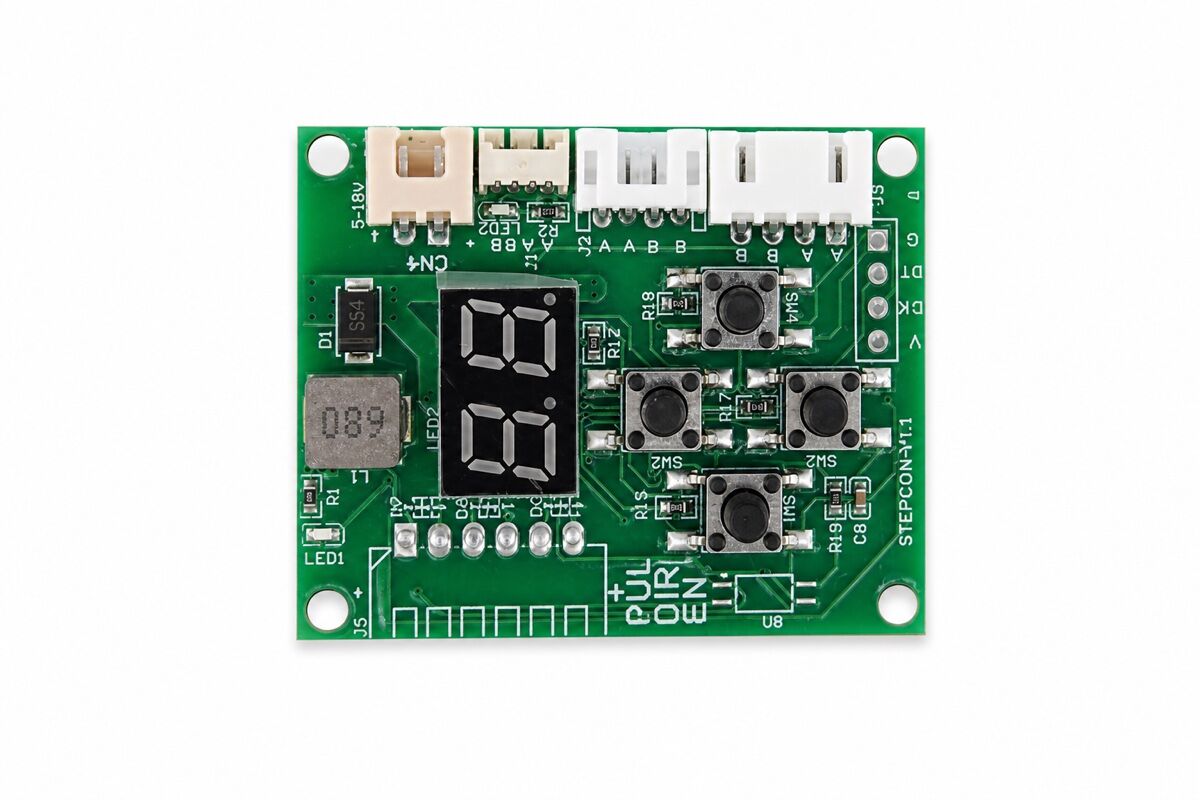
In addition, the board-only dimension drawing helps users check installation space. As a result, it is easier to design the driver into compact equipment.

Also, the main product image shows the stepper motor speed controller style. Therefore, users can review the board form before sample or bulk order.

Other Instructions
Finally, the following instructions help users avoid overload, wrong input voltage, and motor damage. Therefore, they should be checked before installation and operation.
| Item | Instruction |
|---|---|
| 1 | The motor must not be used beyond the limit load, including stall condition. Damage caused by stall is not covered by warranty. |
| 2 | Please match the DC power supply according to the rated input voltage of the product, DC 12V/24V. Over-voltage or under-voltage power supply is prohibited. |
| 3 | When the load torque equals the rated torque, the speed is the rated value. When the actual load exceeds the rated value, the output speed will decrease accordingly. |
| 4 | When selecting the motor, use the rated torque as the main reference to avoid overload operation. |
| 5 | Operation near or beyond the limit load torque may cause damage to the internal structure of the motor. |
| 6 | Reducing the motor speed will directly reduce the output torque, so the working condition requirements should be evaluated in advance. |
| 7 | The motor will generate dB noise during operation. The noise level may fluctuate slightly with speed and load changes, which is normal. |
Operation Safety Notes
- First, avoid stall: Do not run the motor in stall condition.
- In addition, match the voltage: Use a suitable DC power supply for the product.
- Also, check rated torque: Select the motor based on rated torque to avoid overload.
- Next, test the load: Actual load changes can reduce output speed.
- Finally, evaluate noise: Motor noise may change slightly with speed and load.
In short, this stepper motor simple driver is suitable for compact control systems that need speed adjustment, direction control, reciprocating motion, memory function, and DC 5-36V input.
Keywords: drive module, gear motor speed controller, dc gear motor speed regulator controller, dc motor driver, driver for dc motor, motor driver board, dc gear motor driver, dc electric motor controller, drivers machine, mini motor driver, 12v dc motor controller, brushed dc motor esc
1.Payment methods : Paypal, T/T
Shipping:
1.Delivery: DHL/FedEx 3-5 days.
2.Item will be shipped within 1-3 business days after the payment.
3.If you haven’t received the item on the Delivery Time, pls contact us by email if you have any questions. Normally, we will give you a reply within 24 hours, if not, pls check the spam of your email box. We will do our best to help you solve the problems.
4.Please make sure your address is matched with the finally shipping address before you pay.
FAQ
Q: If customized, what information should you provide?
A: You need to provide the basic specification of the motor, such as: Dimensions, Sizes Applications, Voltage, Speed and Torque. It’s better to offer application prototype drawings to us if possible.
Q: What’s your main motors?
A: Diameter 4mm~42mm Dc Micro Motor And Gear Motor, Auto Dc Motor, Electric Motor, Gear Motor, Mini Dc Motor, Brush Dc Motor, Brushless Dc Motor, Spur Gear Motor, Micro Motor, Vibration Motor Etc.
Q: What’s the main application of the micro dc motor?
A: Our mini DC motors are widely used in Home Applications, Office Equipment, Health-Care Application, Sanitation Industry, High-Class Toy, Banking System, Electronic and Electrical Tools, Automation Industry, Bank Equipments, Payment Equipments, Vending Machines, Power Door Lock, Electric Door Lock.

Reviews